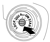
Subaru Outback (BR): Ignition switch
WARNING
● Never turn the ignition switch to “LOCK” while the vehicle is being driven or towed because that will lock the steering wheel, preventing steering control. And when the engine is turned off, it takes a much greater effort than usual to steer.
● Before leaving the vehicle, always remove the key from the ignition switch for safety and never allow an unattended child to remain in the vehicle. Failure to follow this procedure could result in injury to a child or others. Children could operate the power windows, the moonroof or other controls or even make the vehicle move.
CAUTION
Do not attach a large key holder or key case to either key. If it banged against your knees or hands while you are driving, it could turn the ignition switch from the “ON” position to the “Acc” or “LOCK” position, thereby stopping the engine.
Also, if the key is attached to a keyholder or to a large bunch of other keys, centrifugal force may act on it as the vehicle moves, resulting in unwanted turning of the ignition switch.
The ignition switch has four positions: LOCK, Acc, ON and START.

NOTE
● Keep the ignition switch in the “LOCK” position when the engine is not running.
● Using electrical accessories for a long time with the ignition switch in the “ON” or “Acc” position can cause the battery to go dead.
● If the ignition switch will not move from the “LOCK” position to the “Acc” position, turn the steering wheel slightly to the left and right as you turn the ignition switch.

