Subaru Outback (BR): Primary Pulley and Secondary Pulley
A: REMOVAL
NOTE: Always replace primary pulley and secondary pulley as an assembly because they are non-disassembled parts.
1) Remove the transmission assembly from the vehicle. <Ref. to CVT-55, REMOVAL, Automatic Transmission Assembly.>
2) Remove the air breather hose. <Ref. to CVT-132, REMOVAL, Air Breather Hose.>
3) Remove the oil pan and control valve body. <Ref. to CVT-111, REMOVAL, Control Valve Body.>
4) Remove the transmission harness. <Ref. to CVT-121, REMOVAL, Transmission Harness.>
5) Remove the extension case. <Ref. to CVT-138, REMOVAL, Extension Case.>
6) Remove the rear drive shaft. <Ref. to CVT-141, REMOVAL, Rear Drive Shaft.>
7) Remove the transfer clutch assembly. <Ref. to CVT-146, REMOVAL, Transfer Clutch.>
8) Remove the transfer reduction driven gear assembly. <Ref. to CVT-158, REMOVAL, Transfer Reduction Driven Gear.>
9) Remove the intermediate case. <Ref. to CVT-165, REMOVAL, Intermediate Case.>
10) Remove the forward clutch assembly. <Ref. to CVT-180, REMOVAL, Forward Clutch Assembly.>
11) Remove the transmission case. <Ref. to CVT-211, REMOVAL, Transmission Case.>
12) Set the ST to the secondary pulley, and expand the V groove of pulley until the variator chain gets completely loose.
ST 18769AA000 EXPANDER PULLEY

13) Remove the chain guide from lubrication pipe and support rod.
14) Remove the lubrication pipe and support rod.

15) Detach the six claws to remove the two chain guide.

16) Remove the secondary pulley mounting bolt.

17) Remove the secondary pulley from drive pinion retainer and intersect the V groove of secondary pulley and V groove of primary pulley. Remove the variator chain from secondary pulley and remove the secondary pulley.
CAUTION: Cover the V grooves of secondary pulley and primary pulley with cloth to protect the both pulleys and variator chain from scratching.

18) Remove the variator chain from primary pulley.
19) Remove the primary pulley mounting bolt.

20) Remove the primary pulley.
21) Remove the two seal rings from drive pinion retainer.

22) Remove the two seal rings from primary pulley.

B: INSTALLATION
1) Select shims for pulley alignment. <Ref. to CVT-236, ADJUSTMENT, Primary Pulley and Secondary Pulley.>
2) Install the two seal rings to drive pinion retainer.
NOTE:
- Use a new seal ring.
- Apply CVTF to the seal rings.
- When installing the seal ring, do not expand the seal ring too much.

3) Install the selected shims to the primary pulley bearing catch surface.
4) Install the two seal rings to primary pulley.
NOTE:
- Use a new seal ring.
- Apply CVTF to the seal rings.

5) Install the primary pulley and adjust the position of bolt holes of primary bearing retainer and converter case to tighten the primary pulley bolt.
NOTE: Use a new seal washer.
Tightening torque: 21 N*m (2.1 kgf-m, 15.5 ft-lb)

6) Set the ST to secondary pulley and expand the V groove of pulley.
ST1 18769AA000 EXPANDER PULLEY

7) Place the variator chain on the primary pulley groove and attach the secondary pulley and variator chain together to the drive pinion retainer.
CAUTION: Cover the V grooves of primary pulley and secondary pulley with cloth to protect the both pulleys and variator chain from scratching.
- Place the variator chain on primary pulley.
- Intersect the V groove of primary pulley and the V groove of secondary pulley and install the secondary pulley while placing the variator chain on secondary pulley.

- While aligning the bolt hole of secondary bearing retainer and the bolt hole of driving pinion retainer, install the secondary pulley to drive pinion retainer.
8) Install the secondary pulley bolt.
Tightening torque: 33 N*m (3.4 kgf-m, 24.3 ft-lb)

9) Install the chain guide.
NOTE: Install it with two claws facing outward and with four claws facing inward.

10) Engage the cutout portions of support rod and drive pinion retainer and install the support rod.

11) Engage the cutout portions of lubrication pipe and drive pinion retainer and install the lubrication pipe.

12) Install the chain guide so that the lubrication pipe and support rod run through between the protrusions of each chain guide. Then remove the ST (PULLEY EXPANDER).

13) Install the O-ring to the lubrication pipe.
NOTE: Use new O-rings.
14) Install the lubrication pipe.

15) Install the transmission case. <Ref. to CVT-213, INSTALLATION, Transmission Case.>
16) Install the forward clutch assembly. <Ref. to CVT-181, INSTALLATION, Forward Clutch Assembly.>
17) Install the intermediate case. <Ref. to CVT-166, INSTALLATION, Intermediate Case.>
18) Install the transfer reduction driven gear assembly. <Ref. to CVT-158, INSTALLATION, Transfer Reduction Driven Gear.>
19) Install the transfer clutch assembly. <Ref. to CVT-147, INSTALLATION, Transfer Clutch.>
20) Install the rear drive shaft. <Ref. to CVT-141, INSTALLATION, Rear Drive Shaft.>
21) Install the extension case. <Ref. to CVT-138, INSTALLATION, Extension Case.>
22) Install the transmission harness. <Ref. to CVT-123, INSTALLATION, Transmission Harness.>
23) Install the control valve body and oil pan. <Ref. to CVT-115, INSTALLATION, Control Valve Body.>
24) Install the air breather hose. <Ref. to CVT-132, INSTALLATION, Air Breather Hose.>
25) Install the transmission assembly to the vehicle. <Ref. to CVT-70, INSTALLATION, Automatic Transmission Assembly.>
C: INSPECTION
- Check the surface of primary and secondary pulley cones for damage or wear.
- Check the primary and secondary pulley for damage.
- Check the bearing for seizure or wear.
- Apply CVTF to bearing and rotate the bearing to check for noise or dragging etc.
D: ADJUSTMENT
1. PROCEDURE IN REPLACEMENT OF PRIMARY AND SECONDARY PULLEY, OR IN REPLACEMENT OF PRIMARY PULLEY, SECONDARY PULLEY AND VARIATOR CHAIN
1) Measure depth "Lp" from the ST upper face to the primary pulley bearing catch surface at several points and calculate the average.
ST 499575400 GAUGE

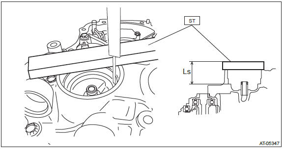
2) Measure height "Ls" from the drive pinion retainer upper face to the secondary pulley bearing catch surface at several points and calculate the average.
ST 499575400 GAUGE
3) Calculate the following formula.
Calculation formula:
T (mm) = B + (Lp - Ls) + 31.601 - A
[T (in) = B + (Lp - Ls) + 1.224 - A]
T: Pulley alignment
A: Specified primary pulley dimension
B: Specified secondary pulley dimension
Lp: Depth from the ST upper face to the primary pulley bearing catch surface
Ls: Depth from the ST upper face to the secondary pulley bearing catch surface
31.601 mm (1.224 in): Constant

4) Select one to two shims so that the total thickness meets the value obtained from step 3).

2. PROCEDURE WHEN REPLACING ONLY DRIVE PINION RETAINER OR CONVERTER CASE
1) Clean the mating surface of current drive pinion retainer and converter case.
2) Measure and record the shim thickness that is attached on the current converter case.
3) Using the current drive pinion retainer, measure depth "Lp1" from the ST upper face to the primary pulley bearing catch surface at several points and calculate the average.
ST 499575400 GAUGE

4) Using the current drive pinion retainer or current converter case, measure depth "Ls1" from the ST upper face to the secondary pulley bearing catch surface at several points and calculate the average.
ST 499575400 GAUGE

5) Calculate the "LD1" using the following formula and record it.
Calculation formula:
LD1 mm (in) = Lp1 - Ls1
LD1: Height from the primary pulley bearing catch surface to the secondary
pulley bearing catch surface
Lp1: Depth from the ST upper face to the primary pulley bearing catch surface
Ls1: Depth from the ST upper face to the secondary pulley bearing catch surface
6) Using the new drive pinion retainer or new converter case, measure depth "Lp2" from the ST upper face to the primary pulley bearing catch surface at several points and calculate the average.
ST 499575400 GAUGE

7) Using the new drive pinion retainer or new converter case, measure depth "Ls2" from the ST upper face to the secondary pulley bearing catch surface at several points and calculate the average.
ST 499575400 GAUGE

8) Calculate the "LD2" using the following formula and record it.
Calculation formula:
LD2 mm (in) = Lp2 - Ls2
LD2: Height from the primary pulley bearing catch surface to the secondary
pulley bearing catch surface
Lp2: Depth from the ST upper face to the primary pulley bearing catch surface
Ls2: Depth from the ST upper face to the secondary pulley bearing catch surface
9) Calculate the recorded values of "LD1" and "LD2" to obtain the positive number to select the shims.
Calculation formula: T1 mm (in) = LD1 - LD2 or T2 mm (in) = LD2 - LD1
T1, T2: Difference between new drive pinion retainer or new converter case and
current drive pinion retainer
or current converter case
LD1: Calculated value of current drive pinion retainer or current converter
case
LD2: Calculated value of new drive pinion retainer or new converter case


Variator Chain
A: REMOVAL
For removal of variator chain, refer to "Primary Pulley and Secondary Pulley". <Ref. to CVT-226, REMOVAL, Primary Pulley and Secondary Pulley.>
B: INSTALLATION
For installation of variator chain, refer to "Primary Pulley and Secondary Pulley". <Ref. to CVT-230, INSTALLATION, Primary Pulley and Secondary Pulley.>
C: INSPECTION
Check the variator chain for damage and wear.
READ NEXT:
 Drive Pinion Shaft Assembly in Continuously Variable Transmission
A: REMOVAL
1) Remove the transmission assembly from the vehicle. <Ref. to CVT-55, REMOVAL, Automatic Transmission Assembly.>
2) Remove the air breather hose. <Ref. to CVT-132, REMOVAL, Air
Front Differential Assembly in Continuously Variable Transmission
A: REMOVAL
1) Remove the transmission assembly from the vehicle. <Ref. to CVT-55, REMOVAL, Automatic Transmission Assembly.>
2) Remove the air breather hose. <Ref. to CVT-132, REMOVAL, Air
Oil Pump
A: REMOVAL
NOTE:
Refer to "Drive Pinion Shaft" for removal procedures. <Ref. to CVT-242, REMOVAL,
Drive Pinion Shaft Assembly.>
B: INSTALLATION
NOTE:
Refer to "Drive Pinion Shaft" for removal p
SEE MORE:
Immobilizer
The immobilizer system is designed to prevent an unauthorized person from starting
the engine. Only keys registered with your vehicle’s immobilizer system can be used
to operate your vehicle. Even if an unregistered key fits into the ignition switch
and can be turned to the “START” posit
Installing child restraint systems with A/ELR seatbelt
WARNING
● Child restraint systems and seatbelts can become hot in a vehicle that has
been closed up in sunny weather; they could burn a small child. Check the child
restraint system before you place a child in it.
● Do not leave an unsecured child restraint system in your vehicle.
