Subaru Outback (BR): ABS Sequence Control
A: OPERATION
1) While the ABS sequence control is being performed, the operation of the hydraulic unit can be checked using the brake tester or pressure gauge after the hydraulic unit solenoid valve operation.
2) ABS sequence control can be started by the Subaru Select Monitor.
1. ABS SEQUENCE CONTROL WITH SUBARU SELECT MONITOR
NOTE: In the event of any trouble, the ABS sequence control will not operate.
1) Connect the Subaru Select Monitor to data link connector.
- Run the "PC application for Subaru Select Monitor".
- On "Main Menu" display, select {Each System Check}.
- Select {Brake Control System}. When {ABS} is displayed, select the [OK] button.
- Select the {ABS Function Check Mode} from {ABS Sequence Control Mode}.
2) Follow the procedures displayed in the Subaru Select Monitor to execute the following.
- When using a brake tester, press the brake pedal pad with a force of 1,000 N (102 kgf, 225 lbf).
- When using a pressure gauge, press the brake pedal so that the pressure gauge indicates 3,500 kPa (36 kgf/cm2, 511 psi).
3) The brake system being operated is displayed on the Subaru Select Monitor.
2. CONDITIONS FOR ABS SEQUENCE CONTROL
NOTE: The control operation starts at point A.
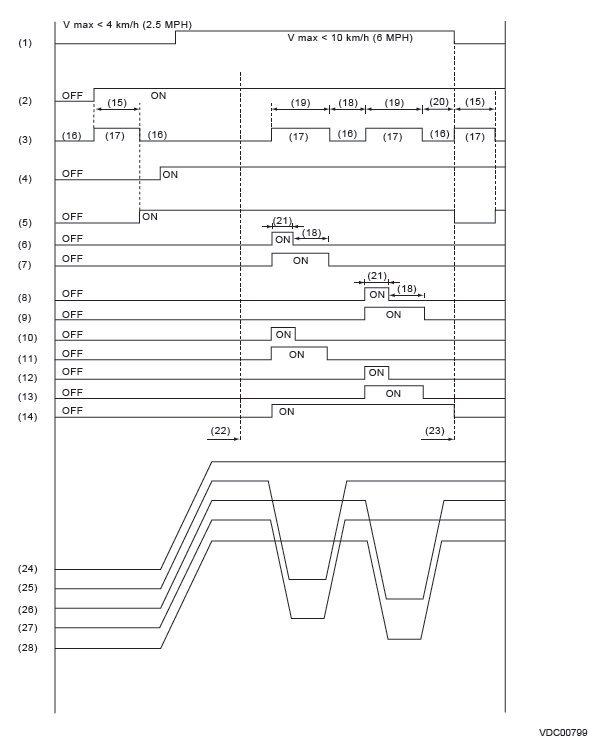
- All wheel speed
- Ignition key
- ABS warning light
- Stop light switch
- Valve relay
- FL decompression valve
- FL compression valve
- FR decompression valve
- FR compression valve
- RR decompression valve
- RR compression valve
- RL decompression valve
- RL compression valve
- Pump motor
- 2 seconds
- Light OFF
- Light ON
- 1.0 second
- 1.4 seconds
- 0.6 seconds
- 0.4 seconds
- Point A
- Reset
- Master cylinder pressure
- FL wheel cylinder pressure
- FR wheel cylinder pressure
- RR wheel cylinder pressure
- RL wheel cylinder pressure
B: SPECIFICATION
1. CONDITIONS FOR COMPLETION OF ABS SEQUENCE CONTROL
When the following conditions develop, the ABS sequence control stops and ABS operation is returned to the normal control mode.
- When the speed of at least one wheel reaches 10 km/h (6 MPH).
- When the brake pedal is released during ABS sequence control and the stop light switch is becomes OFF.
- After completion of ABS sequence control.
- When a malfunction is detected.
VDC Sequence Control
A: OPERATION
1) While the VDC sequence control is performed, the operation of the hydraulic unit can be checked using the brake tester or pressure gauge after the hydraulic unit solenoid valve is operated.
2) VDC sequence control can be started by Subaru Select Monitor.
1. VDC SEQUENCE CONTROL WITH SUBARU SELECT MONITOR
NOTE: In the event of any trouble, sequence control will not operate.
1) Connect the Subaru Select Monitor to data link connector.
- Run the "PC application for Subaru Select Monitor".
- On "Main Menu" display, select {Each System Check}.
- Select {Brake Control System}. When {VDC} is displayed, select the [OK] button.
- Select the {VDC Function Check Mode} from {Function Check Sequence}.
2) Operate according to the procedures displayed in the Subaru Select Monitor.
3) The brake system being operated is displayed on the Subaru Select Monitor.
2. CONDITIONS FOR VDC SEQUENCE CONTROL
NOTE: The control operation starts at point A.
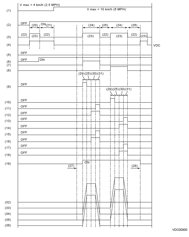
- All wheel speed
- Ignition key
- ABS warning light
- VDC warning light
- Stop light switch
- Valve relay
- VDC switching valve 1 FL
- VDC switching valve 1 FR
- VDC switching valve 2 FL
- VDC switching valve 2 FR
- FL decompression valve
- FL compression valve
- FR decompression valve
- FR compression valve
- RR decompression valve
- RR compression valve
- RL decompression valve
- RL compression valve
- Pump motor
- 2 seconds
- Approx. 1 second
- Light OFF
- Light ON
- 3.4 seconds
- 1 second
- 1.6 seconds
- Point A
- Reset
- 0.8 seconds
- 1.2 seconds
- 0.4 seconds
- Master cylinder pressure
- FR wheel cylinder pressure
- FL wheel cylinder pressure
- RL wheel cylinder pressure
- RR wheel cylinder pressure
B: SPECIFICATION
1. CONDITIONS FOR COMPLETION OF VDC SEQUENCE CONTROL
When the following conditions develop, the VDC sequence control stops and VDC operation is returned to the normal control mode.
- When the speed of at least one wheel reaches 10 km/h (6 MPH).
- After completion of VDC sequence control.
- When a malfunction is detected.
READ NEXT:
 Yaw Rate and G Sensor
A: NOTE
Yaw rate & longitudinal G and lateral G sensor are integrated with the VDC
control module & hydraulic control
module (VDCCM&H/U).
B: INSPECTION
1. YAW RATE & LONGITUDINAL G AN
Front ABS Wheel Speed Sensor
A: REMOVAL
1) Disconnect the ground cable from battery.
2) Lift up the vehicle, and then remove the front wheels.
3) Remove the front ABS wheel speed sensor.
CAUTION:
Be careful not to damage the
SEE MORE:
Electronic parking brake system warning
The brake system warning light flashes when the electronic parking
brake system is malfunctioning. If the warning light flashes, promptly park in a
safe location as soon as possible and contact your SUBARU dealer.
The brake system warning light remains illuminated when the parking
brake canno
Coolant temperature low indicator light/Coolant temperature high warning light
CAUTION
● After turning the ignition switch to the “ON” position, if this indicator light/warning
light behaves under any of the following conditions, the electrical system may be
malfunctioning. Contact your SUBARU dealer immediately for an inspection.
– It remains blinking in RED
