Subaru Outback (BR): Headlight Assembly
A: REMOVAL
CAUTION: Do not perform work with wet hands.
1) Disconnect the ground cable from battery.
2) Remove the clips and remove the air intake duct. (When removing the headlight RH)

3) Remove the front bumper face assembly. <Ref. to EI-39, REMOVAL, Front Bumper.>
4) Remove the fender cover assembly UPR.
- Remove the clip.
- Release the claws of the fender cover assembly UPR by pulling it forward and remove the fender cover.

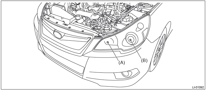
5) Remove the headlight assembly.
- Remove the bolts and clips, and pull out the headlight assembly to the front of the vehicle.

- Disconnect the connector and remove the headlight assembly.
- Headlight connector RH

- Headlight connector LH

B: INSTALLATION
1) Install each part in the reverse order of removal.
Tightening torque: Headlight assembly: 7.5 N*m (0.76 kgf-m, 5.5 ft-lb)
2) Adjust the headlight beam and fog light beam.
- Adjust the headlight beam. <Ref. to LI-27, HEADLIGHT BEAM ADJUSTMENT, ADJUSTMENT, Headlight Assembly.>
- Adjust the fog light beam. (Model with fog light) <Ref. to LI-41, FOG LIGHT AIMING, ADJUSTMENT, Front Fog Light Assembly.>
C: ADJUSTMENT
1. HEADLIGHT BEAM ADJUSTMENT
CAUTION:
- Turn off the light before adjusting the headlight beam level. If it is necessary to inspect the beam level, do not keep the light on for two minutes or more.
- When blocking the light emitted from the headlight, use a light shield or equivalent.
Do not apply the tape on the lens or place the cloth over it. It may raise the temperature in the light and cause deformation/bubble formations of the plastic lens.
1) Before checking the headlight beam level, be sure of the following:
- The area around the headlight has not sustained any scratches, damage or other type of deformation.
- Vehicle is parked on a level surface.
- The inflation pressure of tires is correct.
- Vehicle's fuel tank is fully filled.
2) Bounce the vehicle several times to normalize the suspension.
3) Make certain that someone is seated in the driver's seat.
4) Measure the distance between the low beam bulb centers and the height of the bulb center.
- High beam
- Low beam
5) Place the vehicle with the front end facing to the measurement panel.
NOTE: Adjustment type is recognized by marking of the right and left headlight. Confirm that which is displayed VOL or VOR, and then perform the operation according to the actual adjustment type.
- RH side headlight: Marking is placed at (A) or (B).
- LH side headlight: Marking is placed at (C).

- VOL type

- Vehicle center
- Bulb center marking
- 3 m (10 ft)
- Height of headlight center

- VOR type

- Vehicle center
- Bulb center marking
- 3 m (10 ft)
- Height of headlight center

6) Adjust the headlight low beam by turning the aiming screw.

NOTE: When using a tester, follow the instructions of the tester manual.
READ NEXT:
 Headlight Bulb
A: REMOVAL
1. HIGH BEAM
CAUTION:
Because the halogen bulb operates at a high temperature, dirt and oil
on the bulb surface reduces
the bulb's service life. Hold the flange portion when replacing
Front Side Marker Light Bulb
A: REMOVAL
1) Disconnect the ground cable from battery.
2) Remove the clips and remove the air intake duct. (When removing the front
turn signal light bulb RH)
3) Turn the steering wheel in the opp
Tail/Stop Light Bulb
A: REMOVAL
1. SEDAN MODEL
Rear combination light side
1) Disconnect the ground cable from battery.
2) Release the lock and remove the bulb inspection cover of trunk room trim.
3) Remove the bulb
SEE MORE:
Certification for the Hands-free system
NOTE
● This device complies with Part 15 of the FCC Rules and with RSS-Gen of IC Rules.
Operation is subject to the following two conditions: (1) This device may not cause
harmful interference, and (2) this device must accept any interference received,
including interference that may ca
Propeller Shaft
A: REMOVAL
CAUTION:
Do not disassemble the center EDJ of the propeller shaft.
Before removing propeller shaft, wrap the metal parts attached to the
rubber boot of center EDJ
with a cloth or rubber material, as shown in the figure. The rubber boot may
be damaged due to interference
with adja
