Subaru Outback (BR): Subaru Select Monitor
A: OPERATION
1. HOW TO USE SUBARU SELECT MONITOR
NOTE:
- For detailed operation procedures, refer to "PC application help for Subaru Select Monitor".
- If VDC and Subaru Select Monitor cannot communicate, check the communication circuit. <Ref. to VDC(diag)-20, COMMUNICATION FOR INITIALIZING IMPOSSIBLE, INSPECTION, Subaru Select Monitor.>
2. READ CURRENT DATA
NOTE:
- For detailed operation procedures, refer to "PC application help for Subaru Select Monitor".
- A list of the support data is shown in the following table.
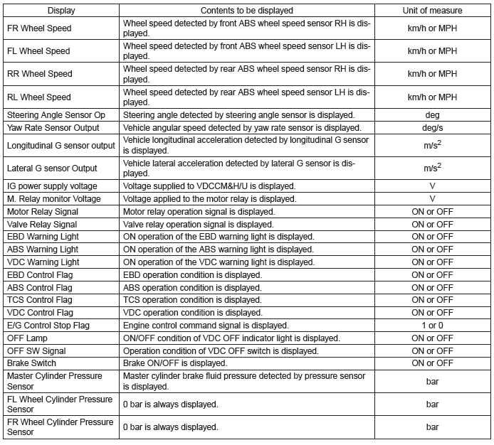
3. FUNCTION CHECK
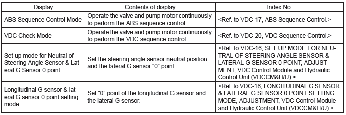
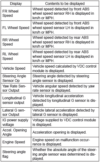
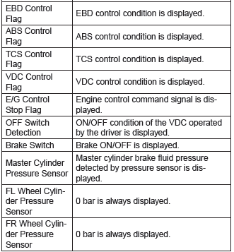
4. FREEZE FRAME DATA
NOTE:
- Data stored at the time of trouble occurrence is shown on display.
- Each time a trouble occurs, the latest information is stored in the freeze frame data in memory.
- If a freeze frame data is not properly stored in memory (due to a drop in VDCCM power supply, etc.), a DTC suffixed with a question mark "?" appears on the Subaru Select Monitor display. This shows it may be an unreliable reading.
5. PARAMETER SELECTION
CAUTION:
- Subaru Select Monitor is required for parameter selection.
- This function can be used for the replacement part of VDCCM&H/U.
NOTE:
- When the VDCCM&H/U is replaced with a replacement part, be sure to perform the parameter selection/registration to the VDCCM&H/U using this function.
- To confirm the applied model, refer to the "model number plate" attached on the vehicle. <Ref. to ID- 2, IDENTIFICATION, Identification.>
- When the applied model is entered wrong, re-entry is possible.
- When the registration has not been performed, the DTC code "Parameter selection error" is detected together with the ABS/EBD/VDC warning light illumination.
1) Connect the Subaru Select Monitor.
2) On "Main Menu" display, select {Each System Check}.
3) On "System Selection Menu" display, select {Brake Control System}.
4) When {VDC} is displayed, select the [OK] button.
5) On "Brake Control Diagnosis" display, select {Select Parameter}.
6) Check the applied model and option code indicated in the "Model number plate". <Ref. to ID-2, IDENTIFICATION, Identification.>
7) Enter the applied model of 7-digit alphanumeric characters and press the [Enter] key.
8) When the option code input screen appears after entering the applied model, enter the option code consisting of 4-digit alphanumeric characters, and press the [Enter] key When the option code is 3 digits, add "0" in front and enter the code as 4 digits.
9) When the confirmation screen indicating the vehicle information appears, check that the correct applied model and grade are displayed and click the [OK] button.
NOTE: When the displayed applied model and grade are different from those of the vehicle, perform registration operations again after clicking the [OK] button.
10) Execute the Clear Memory Mode after parameter selection and registration operations because the DTC for "Parameter selection error" is memorized.
<Ref. to VDC(diag)-25, Clear Memory Mode.>
6. PARAMETER CHECK
NOTE: The parameter data registered in the VDCCM is shown on the display.
1) Connect the Subaru Select Monitor.
2) On the "Main Menu" display, select the {Each System Check}.
3) On the "System Selection Menu" display, select the {Brake Control System}.
4) Click the [OK] button after the {VDC} is displayed.
5) On the "Brake Control Diagnosis" display, select the {Confirm on parameter}.
6) On the {Confirm on parameter} display screen, check that the applied model and grade of the target vehicle are included, and click the [OK] button.
7) If the applied model and grade of the target vehicle are not included on the {Confirm on parameter} display screen, perform parameter selection and registration. <Ref. to VDC(diag)-19, PARAMETER SELECTION, OPERATION, Subaru Select Monitor.>
B: INSPECTION
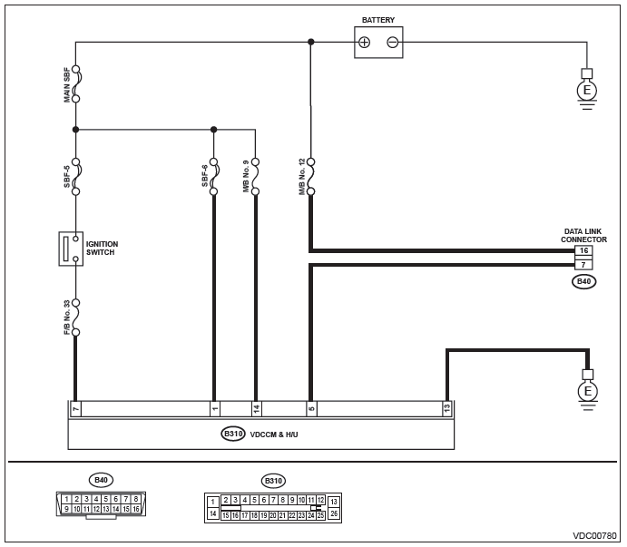
1. COMMUNICATION FOR INITIALIZING IMPOSSIBLE
DETECTING CONDITION:
Defective harness connector
TROUBLE SYMPTOM:
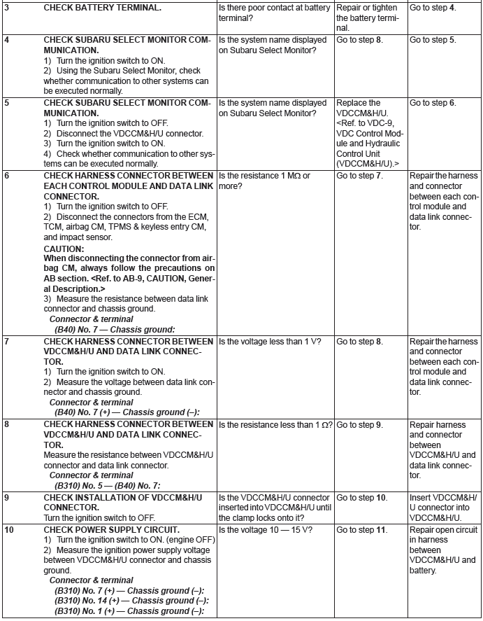
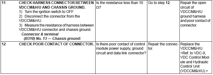
Communication is impossible between VDC and Subaru Select Monitor.
WIRING DIAGRAM:

Read Diagnostic Trouble Code (DTC)
A: OPERATION
NOTE:
- For detailed operation procedures, refer to "PC application help for Subaru Select Monitor".
- For details concerning DTCs, refer to "List of Diagnostic Trouble Code (DTC)". <Ref. to VDC(diag)- 35, List of Diagnostic Trouble Code (DTC).>
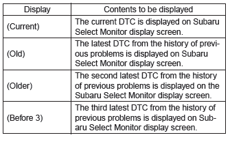
- Up to 3 DTCs are displayed in the order of detection.
- If a particular DTC is not stored in memory properly at the occurrence of problem (due to a drop in VDCCM&H/U power supply etc.), the DTC suffixed with a question mark "?" is displayed on Subaru Select Monitor display screen. This shows it may be an unreliable reading.
Inspection Mode
A: PROCEDURE
Reproduce the malfunction occurrence condition as much as possible.
Drive the vehicle at least ten minutes.
NOTE: Make sure the vehicle is not dragged to one side under usual driving condition.
Clear Memory Mode
A: OPERATION
NOTE: For detailed operation procedures, refer to "PC application help for Subaru Select Monitor".

